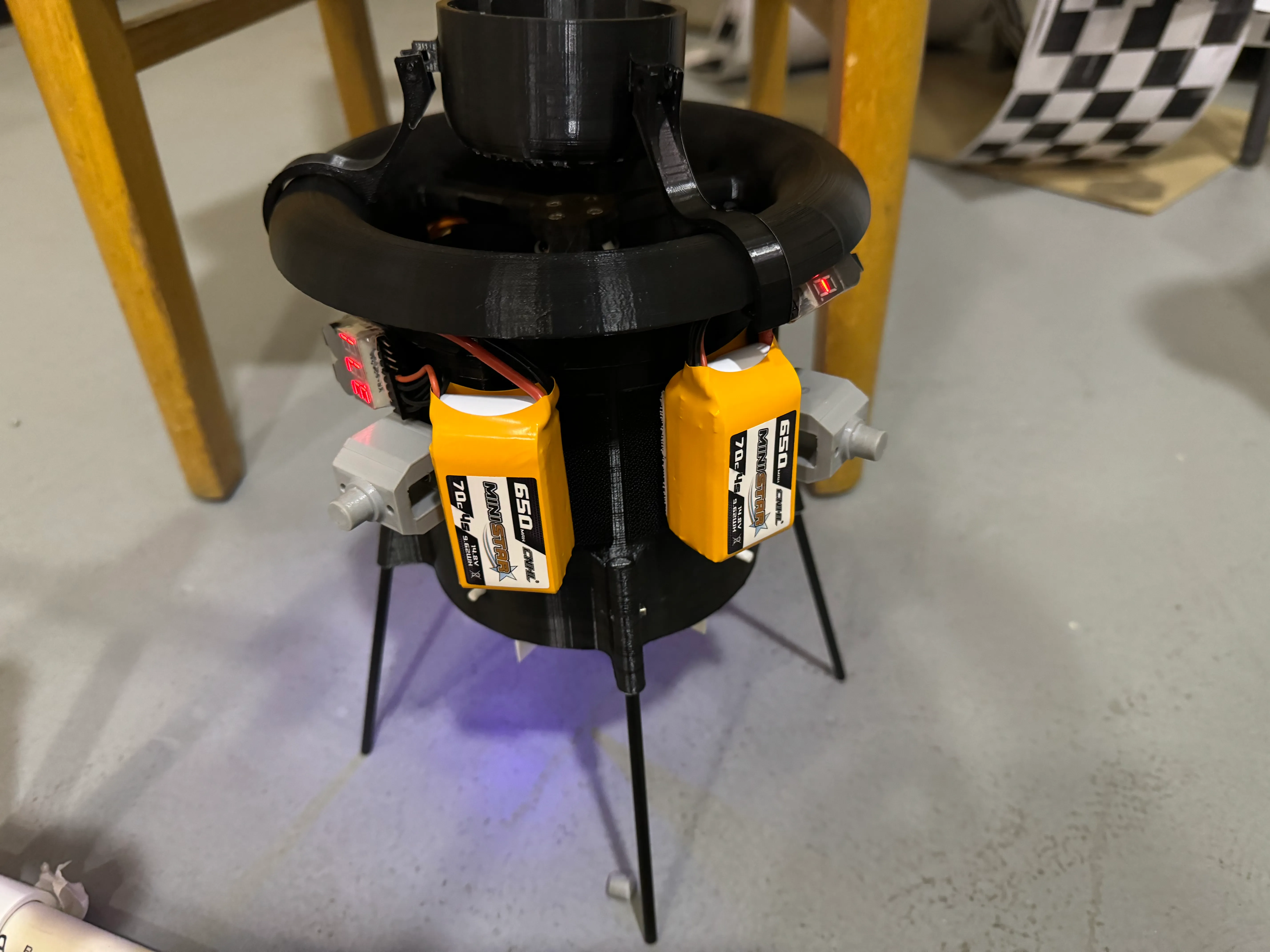
For my undergraduate degree’s two-year capstone course, my team of four was tasked with evaluating the viability of a coaxial two-propeller configuration with an intake duct for a drone similar in size to commonly-available small quadcopters. This configuration was hypothesized to provide additional thrust-to-power efficiency and safety around people with the propeller blades enclosed by the duct. We were asked to produce an autonomous flying prototype that could complete a demo of delivering a beverage indoors, perform testing to evaluate its control torque, thrust, and power consumption, and find design parameters to maximize thrust and control torque.
We split up the prototype build into phases to minimize technical risks of building something that couldn’t fly. After extensive background research to inform our initial design, the first phase was to develop an aerodynamically-representative prototype to use for on-the-ground testing to validate that it could produce enough thrust to lift its own weight and enough control torque to hover in place. Next, the goal was to add electronics to create a flying prototype with attitude stabilization so it could keep itself upright without human intervention. After this, the next phase was adding altitude and position control for autonomous hover.
Since this propeller configuration is not common for hobby drones, we had to custom design the airframe. We used CAD software to design a 3D-printable airframe with mount points for our test stands. The initial prototype for on-the-ground testing used motors, propellers, LiPo batteries, and motor controllers that were already available in the lab. For flight control firmware, we decided early in the project to use ArduPilot because it is an open-source project that already has a control mixer for a two-propeller configuration with thrust vectoring control vanes, supports a wide range of sensors for different levels of autonomy, and already implements sensor fusion algorithms. I led component selection for later prototypes, and selected a flight controller module that had ArduPilot support and an integrated power distribution board that could output 5 V at a high enough current for the thrust vectoring servo motors, an optical flow sensor, and BLDC motors that were better matched to our larger, slower, high blade pitch propellers. I also led electronics bringup and integration, soldering the motors to our motor controllers, configuring our flight control firmware for our motor controllers, calibrating servo limits, calibrating the upright position for the flight controller’s IMU, and setting pinouts and baud rate for our Bluetooth serial adapter.
Finding design parameters to maximize thrust required us to design, build, and program a custom test jig to measure thrust and power consumption while sweeping through throttle levels, and allow us to quickly swap components between tests. We constructed a horizontal test platform with low-friction linear bearings to constrain motion only in the axial direction and support the weight of the components without it contributing to the thrust measurement, then connected the prototype to a load cell with fishing line. One design parameter, propeller tip-to-duct clearance, required sub-mm precision beyond the capabilities of our FDM 3D printer, so one of my teammates machined an aluminum duct and machined several propellers down to different radii for these tests. We used an ESP32 microcontroller to control the throttle on our motor controllers, read thrust data from the load cell amplifier, voltage data from the voltage divider on the battery, and current data from a shunt resistor. I contributed to the Arduino firmware for the test stand. The sensor data from the test stand was sent to a computer over UART and we wrote a Python program to save the results to CSV. I wrote Jupyter notebooks using Python and Pandas to aggregate data from different tests to graph and compare various performance measures between test runs.
We faced several challenges throughout the project. It became clear when starting to tune PID control for altitude control that the barometer integrated into the flight controller would not provide precise enough altitude readings indoors, so we purchased an ultrasonic rangefinder. During integration of the new rangefinder, we found that the readings were very reliable when the motors were turned off, but became erratic once they were turned on, which required us to switch technologies again and ultimately use a ToF laser rangefinder. This was sufficient in the end, but a trade-off was a lower maximum altitude. The initial goal of the project was to implement autonomous localization, mapping, and path planning for the drone to autonomously fly between two points, but this was ultimately cut from the project scope to focus more on aerodynamic testing.
At the end of the project, we successfully demoed an indoor beverage delivery (video below) with the drone capable of autonomous hover without needing human intervention for several seconds, and remote controlled takeoff, forward flight, and landing. We also produced a report detailing the findings of our aerodynamic testing, and had power consumption and thrust results for multiple values of several design parameters, including propeller tip-to-duct clearance, propeller radius, propeller blade pitch, and duct lip radius.
Tooling and results from the project can be found on GitHub